Document #SPEC-2306-VSB
OUTPUT #1 (BATTERY)
DC VOLTAGE OUTPUT (2 YEARS, 23°C ± 5°C)
OUTPUT VOLTAGE: 0 to +15VDC.
OUTPUT ACCURACY: ±(0.05% + 3mV).
PROGRAMMING RESOLUTION: 1mV.
READBACK ACCURACY1: ±(0.05% + 3mV).
READBACK RESOLUTION: 1mV.
LOAD REGULATION: ±(0.01% + 2mV).
LINE REGULATION: ±(0.5mV).
STABILITY2: ±(0.01% + 0.5mV).
MEASUREMENT TIME CHOICES: 0.01 to 10 PLC7, in 0.01PLC steps.
AVERAGE READINGS: 1 to 10.
READING TIME1, 8, 9: 31ms, typical
| TRANSIENT RESPONSE: | High Bandwidth | Low Bandwidth |
| Transient Recovery Time13 | <40µs3 or <60µs4 | <80µs3 or <100µs4 |
| Transient Voltage Drop | <75mV3 or <100mV4 | <250mV3 or <400mV4 |
REMOTE SENSE: 1V max. drop in each lead. Add 2mV to the voltage load regulation specification for each 1V change in the negative output lead due to load current change. Remote sense required. Integrity of connection continually monitored. If compromised, output will turn off automatically once settable window (±0 to ±8 volts) around normal voltage exceeded.
VARIABLE OUTPUT IMPEDANCE
RANGE: 0 to 1.00Ω in 0.01Ω steps. Value can be changed with output on if trigger external disabled on channel.
DC CURRENT (2 YEARS, 23°C ± 5°C)
CONTINUOUS AVERAGE OUTPUT CURRENT:
Channel #2 (Charger) OFF: I = 50W/(Vset channel 1 + 6V); 5A max.
Channel #2 (Charger) ON: I = (50W – Power consumed by channel #2)/(Vset channel 1 + 6V); 5A max.
The power consumed by channel #2 is calculated as:
Channel #2 sourcing current: Power consumed = (Vset channel 2 + 6V) × (current supplied)
Channel #2 sinking current: Power consumed = 5 × (sink current)
Peak currents can be a maximum of 5A provided the average current is within the above limits.
CONTINUOUS AVERAGE SINK CURRENT:
Channel #2 (Charger) OFF:
0–5V: 3A max.
5–15V: Derate 0.2A per volt above 5V. Compliance setting controls sinking.
Channel #2 (Charger) ON:
Available current = (50W – Power consumed by channel #2)/5; 3A max. (0–5V).
Derate 0.2A per volt above 5V.
SOURCE COMPLIANCE ACCURACY: ±(0.16% + 5mA)5.
PROGRAMMED SOURCE COMPLIANCE RESOLUTION: 1.25mA.
READBACK ACCURACY1:
5A Range: ±(0.2% + 200µA).
5mA Range: ±(0.2% + 1µA).
READBACK RESOLUTION:
5A Range: 100µA.
5mA Range: 0.1µA.
LOAD REGULATION: ±(0.01% + 1mA).
LINE REGULATION: ±(0.5mA).
STABILITY4 : ±(0.01% + 50µA).
MEASUREMENT TIME CHOICES: 0.01 to 10 PLC7, in 0.01PLC steps.
AVERAGE READINGS: 1 to 10.
READING TIME1, 8, 9: 31ms, typical.
PULSE CURRENT MEASUREMENT OPERATION
TRIGGER LEVEL:
5A Range: 5mA to 5A, in 5mA steps.
1A Range: 1mA to 1A, in 1mA steps.
100mA Range: 0.1mA to 100mA, in 100µA steps.
TRIGGER DELAY: 0 to 100ms, in 10µs steps.
INTERNAL TRIGGER DELAY: 15µs.
HIGH/LOW/AVERAGE MODE:
Measurement Aperture Settings: 33.3µs to 833ms, in 33.3µs steps.
Average Readings: 1 to 100.
PULSE CURRENT MEASUREMENT ACCURACY11 (2 Years, 23°C ±5°C):
| Aperture | Accuracy ±(% reading + offset + rms noise10) |
| <100 µs | 0.2% + 900 µA + 2mA |
| 100 µs – 200 µs | 0.2% + 900 µA + 1.5mA |
| 200 µs – 500 µs | 0.2% + 900 µA + 1mA |
| 500 µs – <1 PLC | 0.2% + 600 µA + 0.8mA |
| 1 PLC12 | 0.2% + 400 µA + 0mA |
| >1 PLC | 0.2% + 400 µA + 100µA |
BURST MODE CURRENT MEASUREMENT
MEASUREMENT APERTURE: 33.3µs to 833ms, in 33.3µs steps.
CONVERSION RATE: 3650/second at 33.3µs meas. aper., typical.
INTERNAL TRIGGER DELAY: 15µs with 33µs.
NUMBER OF SAMPLES: 1 to 5000.
TRANSFER SAMPLES ACROSS IEEE BUS IN BINARY MODE: 4800 bytes/s, typical.
LONG INTEGRATION MODE CURRENT MEASUREMENT
MEASUREMENT TIME6: 850ms (840ms) to 60 seconds in 1ms steps.
DIGITAL VOLTMETER INPUT (2 YEARS, 23°C ± 5°C)
INPUT VOLTAGE RANGE: –5 to +30VDC.
INPUT IMPEDANCE: 2MΩ typical.
MAXIMUM VOLTAGE (either input terminal) WITH RESPECT TO OUTPUT LOW: –5V, +30V.
READING ACCURACY1: ±(0.05% + 3mV).
READING RESOLUTION: 1mV.
CONNECTOR: HI and LO input pair part of Output #1’s terminal block.
MEASUREMENT TIME CHOICES: 0.01 to 10 PLC7, in 0.01PLC steps.
AVERAGE READINGS: 1 to 10.
READING TIME1, 8, 9: 31ms, typical.
VOLTAGE SETTLING TIMES
Voltage Step Settling Times —Typical
| Increasing Voltage | 10-90% Rise Time | Settling Time |
| Voltage step ≤ 7V |
50µs | 300µs |
| Voltage step > 7V | 50µs to 1.2ms | 300µs to 1.8ms |
| Decreasing Voltage | 10-90% Fall Time | Settling Time |
| 0V < Voltage step < 15V | 50µs to 250µs | 300µs |
NOTE: Times are under no load condition and settling times defined at ±2% of step size.
OUTPUT #2 (CHARGER)
DC VOLTAGE OUTPUT (2 YEARS, 23°C ± 5°C)
OUTPUT VOLTAGE: 0 to +15VDC.
OUTPUT ACCURACY: ±(0.05% + 10mV).
PROGRAMMING RESOLUTION: 10mV.
READBACK ACCURACY1: ±(0.05% + 3mV).
READBACK RESOLUTION: 1mV.
OUTPUT VOLTAGE SETTLING TIME: 5ms to within stated accuracy.
LOAD REGULATION: ±(0.01% + 2mV).
LINE REGULATION: ±(0.5mV).
STABILITY2: ±(0.01% + 0.5mV).
MEASUREMENT TIME CHOICES: 0.01 to 10 PLC7, in 0.01PLC steps.
AVERAGE READINGS: 1 to 10.
READING TIME1, 8, 9: 31ms, typical
| TRANSIENT RESPONSE: | High Bandwidth | Low Bandwidth |
| Transient Recovery Time13 | <50µs3 or <80µs4 | <60µs3 or <100µs4 |
| Transient Voltage Drop | <120mV3 or <150mV4 | <160mV3 or <200mV4 |
REMOTE SENSE: 1V max. drop in each lead. Add 2mV to the voltage load regulation specification for each 1V change in the negative output lead due to load current change. Remote sense required. Integrity of connection continually monitored. If compromised, output will turn off automatically once settable window (±0 to ±8 volts) around normal voltage exceeded.
DC CURRENT (2 YEARS, 23°C ± 5°C)
CONTINUOUS AVERAGE OUTPUT CURRENT:
Channel #1 (Battery) OFF:
I = 50W/(Vset channel 1 + 6V); 5A max.
Channel #1 (Battery) ON:
I = (50W – Power consumed by channel #2)/(Vset channel 1 + 6V); 5A max.
The power consumed by channel #1 is calculated as:
Channel #1 sourcing current: Power consumed = (Vset channel 2 + 6V) × (current supplied)
Channel #1 sinking current: Power consumed = 5 × (sink current)
Peak currents can be a maximum of 5A provided the average current is within the above limits.
CONTINUOUS AVERAGE SINK CURRENT:
Channel #1 (Battery) OFF:
0–5V: 3A max.
5–15V: Derate 0.2A per volt above 5V. Compliance setting controls sinking.
Channel #1 (Battery) ON:
Available current = (50W – Power consumed by channel #1)/5; 3A max. (0–5V).
Derate 0.2A per volt above 5V.
SOURCE COMPLIANCE ACCURACY: ±(0.16% + 5mA)5.
PROGRAMMED SOURCE COMPLIANCE RESOLUTION: 1.25mA.
READBACK ACCURACY1:
5A Range: ±(0.2% + 200µA).
5mA Range: ±(0.2% + 1µA).
READBACK RESOLUTION:
5A Range: 100µA.
5mA Range: 0.1µA.
LOAD REGULATION: ±(0.01% + 1mA).
LINE REGULATION: ±(0.5mA).
STABILITY4 : ±(0.01% + 50µA).
MEASUREMENT TIME CHOICES: 0.01 to 10 PLC7, in 0.01PLC steps.
AVERAGE READINGS: 1 to 10.
READING TIME1, 8, 9: 31ms, typical.
PULSE CURRENT MEASUREMENT OPERATION
TRIGGER LEVEL: 5mA to 5A, in 5mA steps.
TRIGGER DELAY: 0 to 100ms, in 10µs steps.
INTERNAL TRIGGER DELAY: 15µs.
HIGH/LOW/AVERAGE MODE:
Measurement Aperture Settings: 33.3µs to 833ms, in 33.3µs steps.
Average Readings: 1 to 100.
PULSE CURRENT MEASUREMENT ACCURACY11 (2 Years, 23°C ±5°C):
| Aperture | Accuracy ±(% reading + offset + rms noise10) |
| <100 µs | 0.2% + 900 µA + 2mA |
| 100 µs – 200 µs | 0.2% + 900 µA + 1.5mA |
| 200 µs – 500 µs | 0.2% + 900 µA + 1mA |
| 500 µs – <1 PLC | 0.2% + 600 µA + 0.8mA |
| 1 PLC12 | 0.2% + 400 µA + 0mA |
| >1 PLC | 0.2% + 400 µA + 100µA |
BURST MODE CURRENT MEASUREMENT
MEASUREMENT APERTURE: 33.3µs to 833ms, in 33.3µs steps.
CONVERSION RATE: 2040/second at 33.3µs meas. aper., typical.
INTERNAL TRIGGER DELAY: 15µs with 33µs.
NUMBER OF SAMPLES: 1 to 5000.
TRANSFER SAMPLES ACROSS IEEE BUS IN BINARY MODE: 4800 bytes/s, typical.
LONG INTEGRATION MODE CURRENT MEASUREMENT
MEASUREMENT TIME 6: 850ms (840ms) to 60 seconds in 1ms steps.
DIGITAL VOLTMETER INPUT (2 YEARS, 23°C ± 5°C)
INPUT VOLTAGE RANGE: –5 to +30VDC.
INPUT IMPEDANCE: 2MΩ typical.
MAXIMUM VOLTAGE (either input terminal) WITH RESPECT TO OUTPUT LOW: –5V, +30V.
READING ACCURACY1: ±(0.05% + 3mV).
READING RESOLUTION: 1mV.
CONNECTOR: HI and LO input pair part of Output #2’s terminal block.
MEASUREMENT TIME CHOICES: 0.01 to 10 PLC7, in 0.01PLC steps.
AVERAGE READINGS: 1 to 10.
READING TIME1, 8, 9: 31ms, typical.
VOLTAGE SETTLING TIMES
Voltage Step Settling Times —Typical
| Increasing Voltage | 10-90% Rise Time | Settling Time |
| Voltage step ≤ 7V |
10µs | 100µs |
| Voltage step > 7V | 10µs to 1.2ms | 100µs to 1.5ms |
| Decreasing Voltage | 10-90% Fall Time | Settling Time |
| 0V < Voltage step < 15V | 5µs to 40µs | 50µs to 200µs |
NOTE: Times are under no load condition and settling times defined at ±2% of step size.
1 PLC = 1.00.
2 Following 15 minute warm-up, the change in output over 8 hours under ambient temperature, constant load, and line operating conditions.
3 Remote sense, at output terminals, 0.5A to 5A typical.
4 Remote sense, with 4.5m (15 ft) of 16 gauge (1.31mm2) wire and 1Ω resistance in each lead to simulate typical test environment, 1.5A load change (0.15A to 1.65A).
5 Minimum current in constant current mode is 6mA.
6 60Hz (50Hz).
7 PLC = Power Line Cycle. 1PLC = 16.7ms for 60Hz operation, 20ms for 50Hz operation.
8 Display off.
9 Speed includes measurement and binary data transfer out of GPIB.
10 Typical values, peak-to-peak noise equals 6 times rms noise.
11 Based on settled signal: 100µs pulse trigger delay.
12 Also applies to other apertures that are integer multiples of 1PLC.
13 Recovery to within 20mV of previous level.
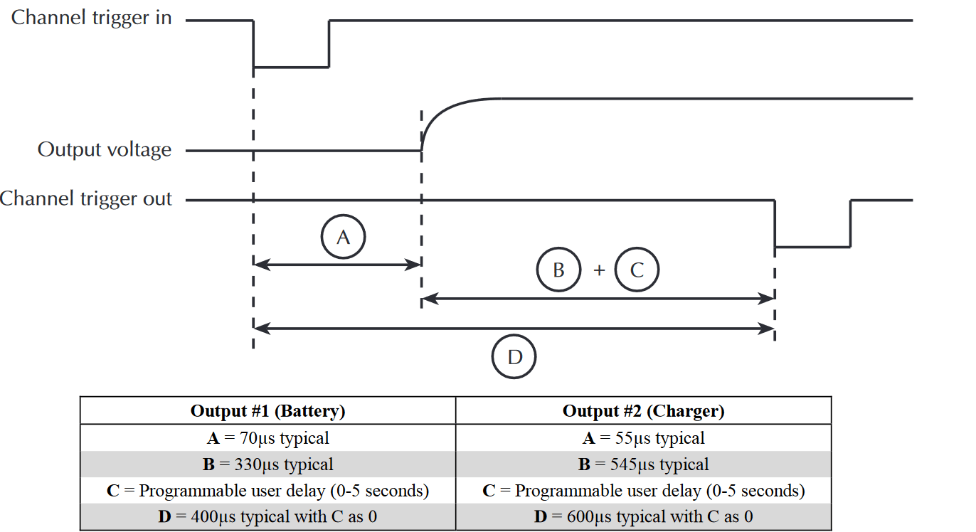
VOLTAGE STEPPING ONLY
TEST CONDITIONS:
- Trigger external is enabled on both channels.
- Only a single channel is externally triggered during the sequence while remaining channel stays idle.
- Times based on 0 programmable user delay
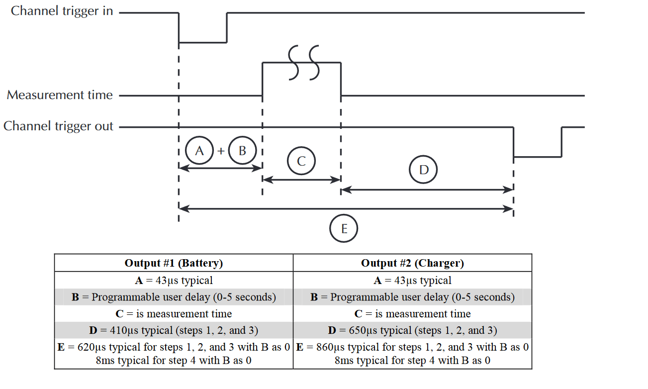
AUTO MEASUREMENT ONLY
TEST CONDITIONS:
- Trigger external is enabled on both channels.
- Only a single channel is externally triggered during the sequence while remaining channel stays idle.
- Times based on 0 programmable user delay.
- Measurement time = 167µs (0.01 plc).
- Steps points = 4.
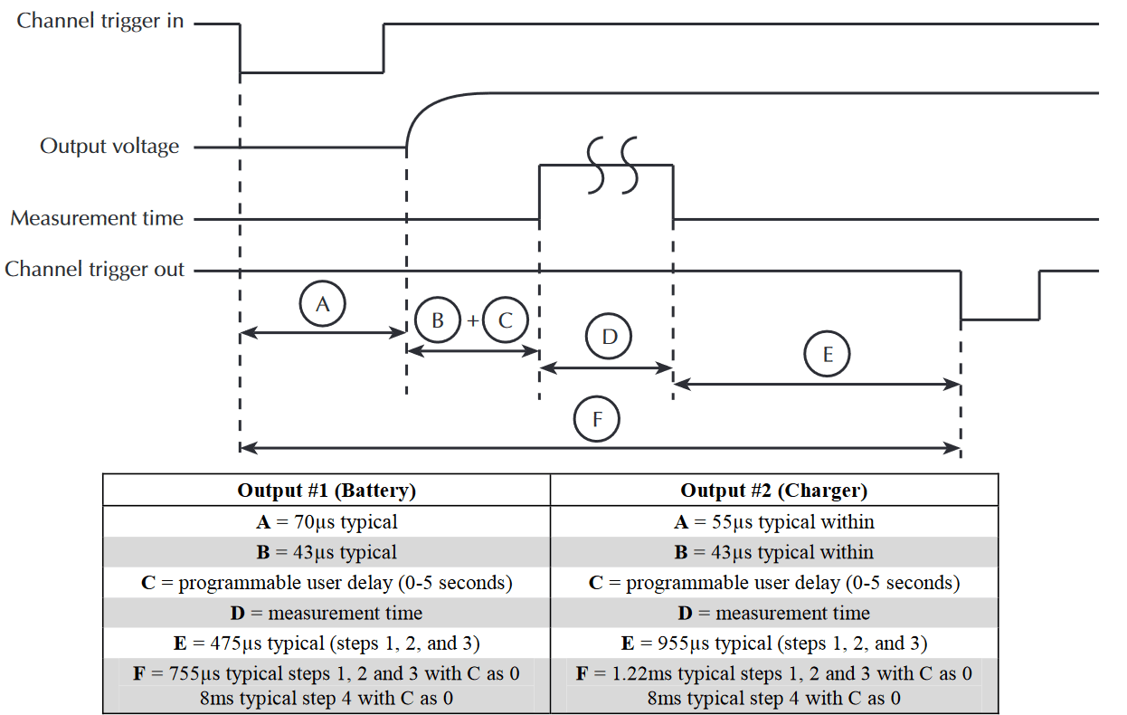
VOLTAGE STEPPING WITH AUTO MEASUREMENT
TEST CONDITIONS:
- Trigger external is enabled on both channels.
- Only a single channel is externally triggered during the sequence while remaining channel stays idle.
- Times based on 0 programmable user delay.
- Measurement time = 167µs (0.01 plc).
- Steps points = 4.
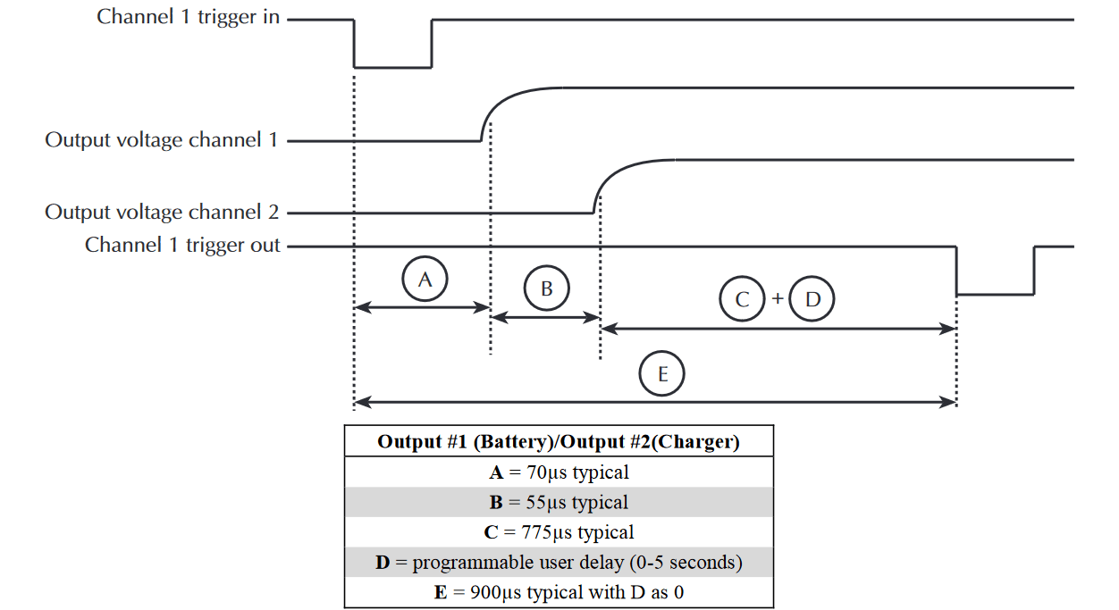
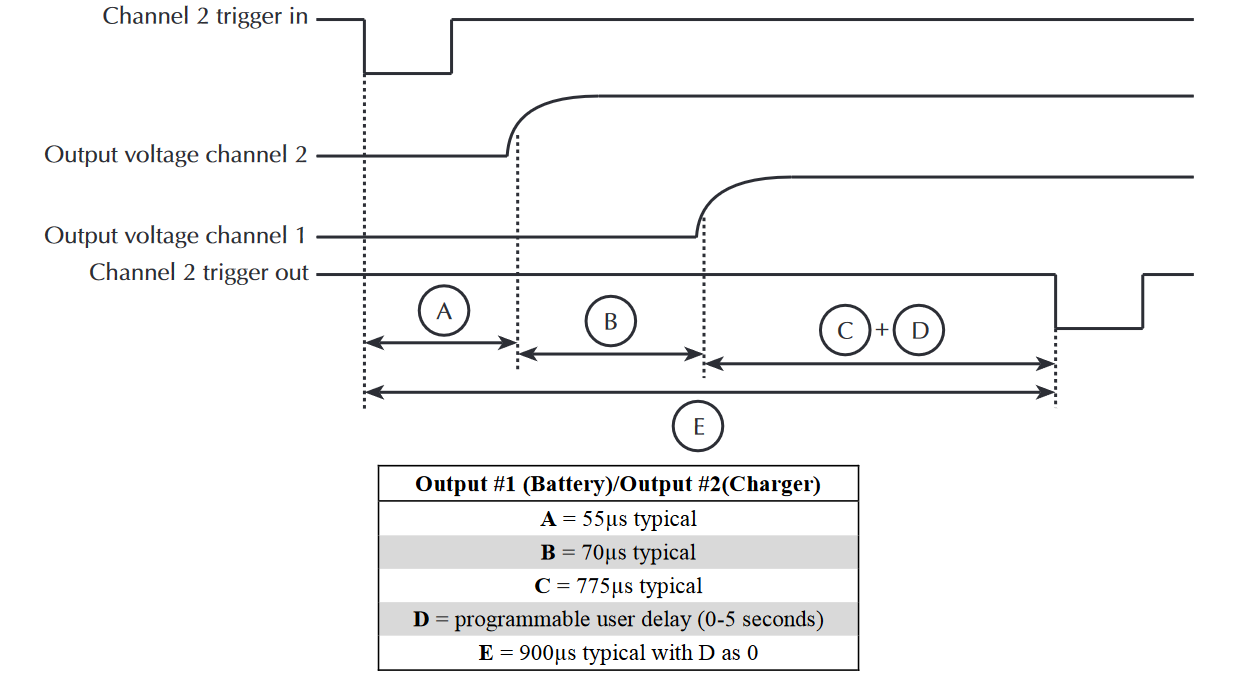
VOLTAGE STEPPING BOTH CHANNELS WITH CHANNEL 1
TEST CONDITIONS:
- Only a single channel is externally triggered during the sequence while remaining channel stays idle.
- Times based on 0 programmable user delay.
VOLTAGE STEPPING BOTH CHANNELS WITH CHANNEL 2
TEST CONDITIONS:
- Only a single channel is externally triggered during the sequence while remaining channel stays idle.
- Times based on 0 programmable user delay.
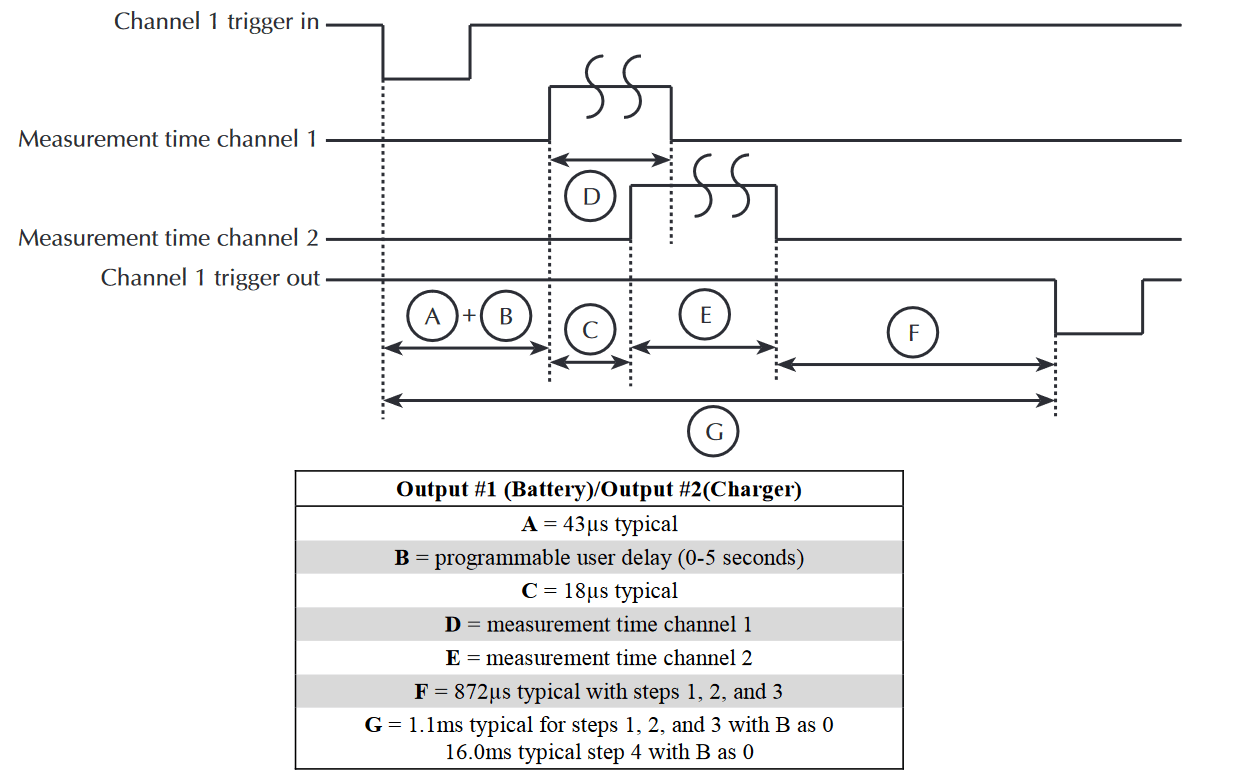
AUTO MEASUREMENT BOTH CHANNELS WITH CHANNEL 1
TEST CONDITIONS:
- Only a single channel is externally triggered during the sequence while remaining channel stays idle.
- Times based on 0 programmable user delay.
- Measurement time = 167µs (0.01 plc).
- Steps points = 4.
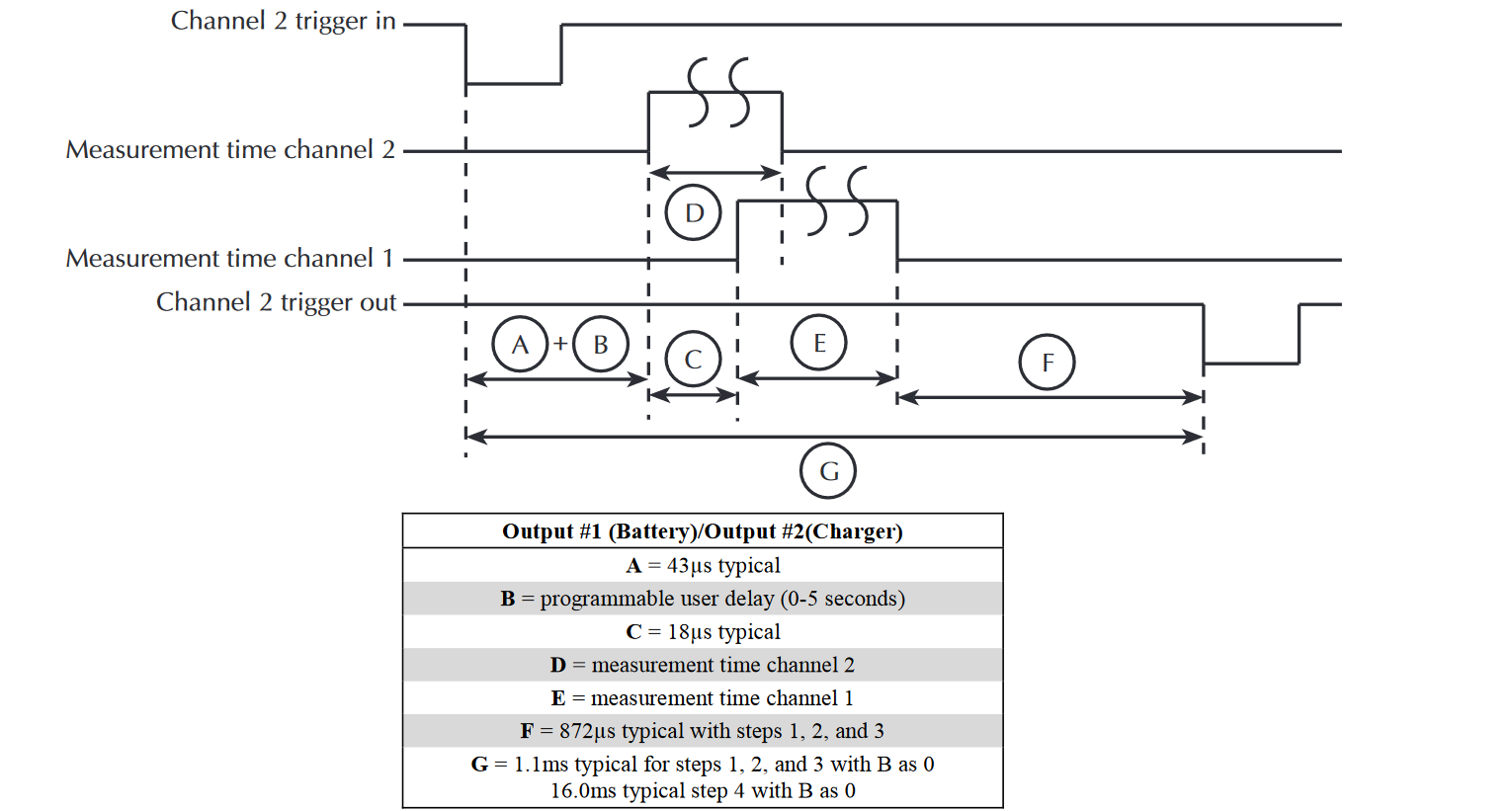
AUTO MEASUREMENT BOTH CHANNELS WITH CHANNEL 2
TEST CONDITIONS:
- Only a single channel is externally triggered during the sequence while remaining channel stays idle.
- Times based on 0 programmable user delay.
- Measurement time = 167µs (0.01 plc).
- Steps points = 4.
VOLTAGE STEPPING WITH SYNC MEASUREMENT
TEST CONDITIONS:
- Trigger external is enabled on both channels.
- Only a single channel is externally triggered during the sequence while remaining channel stays idle.
- Times based on 0 programmable user delay.

GENERAL
ISOLATION (LOW–EARTH): 22VDC max. Do not exceed 60VDC between any two terminals of either connector.
PROGRAMMING: IEEE-488.2 (SCPI).
USER-DEFINABLE POWER-UP STATES: 3.
REAR PANEL CONNECTORS: Two trigger in and two trigger out (BNC) connectors. Two 8-position quick disconnect terminal block for output (4), sense (2), and DVM (2).
TRIGGER IN/OUT CONNECTORS: IN High 3-5V, IN Low ≤0.8V, OUT High >4V, OUT Low <0.8V.
TEMPERATURE COEFFICIENT (OUTSIDE 23°C ±5°C): Derate accuracy specification by (0.1 x specification)/°C.
OPERATING TEMPERATURE: 0° to 50°C (Derate to 70%). 0° to 35°C (Full power).
STORAGE TEMPERATURE: –20° to 70°C.
HUMIDITY: <80% @ 35°C non-condensing.
DISPLAY TYPE: 2-line x 16 character VFD.
DIMENSIONS: 89mm high x 213mm wide x 411mm deep (3.5 in x 8.39 in x 16.18 in).
NET WEIGHT: 3.9kg (8.6lbs.)
SHIPPING WEIGHT: 6.4kg (14lbs.)
INPUT POWER: 100–120VAC/220–240VAC, 50 or 60Hz (auto detected at powerup).
POWER CONSUMPTION: 165VA max.
EMC: Conforms with European Union Directive directive 89/336/EEC, EN 61326.
SAFETY: Conforms with European Union Directive 73/23/EEC, EN 61010-1.
VIBRATION: MIL-PRF-28800F Type III, Class 3