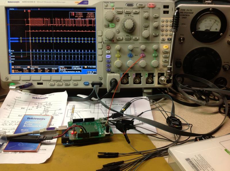
Recently, I had the opportunity to work on a project involving an Arduino Uno with Atmel ATmega328 microcontroller with SPI bus to an RFM12B module, an ISM band FSK transceiver. As usual, there were hardware and software issues to work through. As you’ll see, the MDO4000 mixed domain oscilloscope helped identify the root cause of a noise problem. Here’s the set-up I used:

Here’s screen capture showing what was happening during a packet transmission:

The orange trace labeled A is the RF amplitude versus time, captured using a simple antenna attached to the spectrum analyzer input. The SPI bus was probed using digital logic channels, and a single shot acquisition was triggered on the SPI bus command to transmit. Since this is FSK, frequency shift keying, ideally the RF amplitude should be constant. But we can see that it’s not. Next I added the Frequency versus Time trace, labeled F:

The burst of noise in the upper left is the Frequency versus Time, before the transmission. I used the squelch feature to clean that up:

OK, so the FSK looks good, but the RF amplitude versus time shows apparent crosstalk from SPI bus activity to the RF transmitter power. I suspected ground and/or power rail bounce, so I used a TDP1500 differential probe to measure Vcc to ground:

Sure enough, about 1 Vpp of noise when the transmitter is on. So I zoomed in, using the Wave Inspector knobs, and turned on cursors:

I could see noise on the power supply increases as the RF transmitter turned on. I used the cursors to measure the period of the noise to be about 64 ns. And that coincides with the crystal oscillator. So then I knew that my power distribution needed better bypassing, especially around 16 MHz. Since this was just a proto-board, with no power planes, I wasn’t too concerned. I added a couple ceramic capacitors in additional to the electrolytic after the regulator IC, and that fixed the problem.
Now, if only software debug was this easy!
Since publishing the above blog, Tektronix is currently offering discounts up to 89% on software application modules for qualifying oscilloscopes. Check out the details here and save away!